Ultim809 the ultimate homemade 8-bit computer

For those of you who missed the era of the 8-bit computers here’s your chance to experience the wonders of 8-bit computing through the ongoing project named Ultim809 – the ultimate 8-bit computer.

The Ultim809 project was launched in January of 2010, for its core processor it uses a Motorola 68B09E running at 2MHz. Unlike your common 8-bit computer, the Ultim809 has a 512KByte bank switched network of SRAM chips, bank switching is used since 8-bit computers only support up to 64Kbytes. It has support for graphics, sound, IO-peripherals like keyboards, mouse and joy sticks. It also has secure digital (SD) card support for data storage and finally an ethernet module for network communications. Before I forget just like the large board 8-bit computers Ultim809 also used glue logic integrated circuits, does the 74HC and 74LS series ring a bell? We will be waiting till its completion, and we are anxious to see it pass the test as the ultimate 8-bit computer.

Reading Temperature from DS1820 using 1-Wire Protocol

Temperature sensors come in various shapes and sizes, they also come in different colors and number of pins but above all these differences one difference must not be taken for granted- how to read the temperature data from it. Maybe the simplest form of a temperature sensor is the thermistor, it has two wires, and the resistances between these two wires vary depending on the temperature. This type of sensor requires an ADC to convert the analog signal into digital. However modern temperature sensors now come with their built in ADC and their outputs can be accessed serially. There are three commonly used serial protocols SPI, I2C and 1 Wire, these vary on the number of wires and on the way data is accessed.

In this project the DS1820 is used to demonstrate how to read temperature data from a temperature sensor which communicates using the 1-Wire protocol. The DS1820 is a three pinned temperature sensor, it actually looks more like a transistor – but it’s not! PIC16F628A was used to read the temperature data from the sensor, after data is read it will then be displayed in a 16×2 LCD. The 1-Wire library of MicroC was used to code the firmware for this project.

Digital tachometer using PIC16F628A

Tachometer is an instrument that measures the rotational speed of any shaft or disc in revolutions per minute (RPM) unit. One traditional method of finding the RPM of a rotating shaft is to hook a dynamo with the shaft, and the voltage induced by the dynamo is proportional to the RPM of the shaft. However, this technique may not be applicable every time as it requires a physical contact with the rotating shaft.

Here’s a project that describes a contact-less tachometer based on PIC16F628A microcontroller. The rotation of a disc is measured through a set of IR module that converts a rotation into a pulse. All you have to do is to stick a reflective surface (a piece of plain white paper) at one place on the shaft and bring the IR module facing to the shaft. This will reflect the incident IR beam. In every rotation, the reflective surface will once passes through the module and generate a pulse. These pulses will be counted by the PIC microcontroller, and displayed in to a multiplexed seven segment display. The firmware is written in C and is available for free.

Controlling AVR I/O ports with AVR-GCC

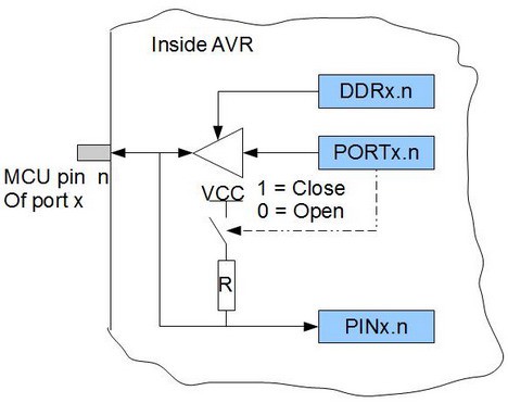
Controlling pins is one of the first things to learn when learning microcontrollers. It seems that each microcontroller type has its own port logic’s. So before using them it is important to understand every detail of it so you could efficiently use in projects. Let’s see how ports are organized in AVR and how successfully control them.

Inside AVR port

If you try to look in to any AVR datasheet you will find port drawing which may seem a bit complex at the start. But for a simple start let’s look at simplified port pin schematic.


x designates port (A,B,S,D,…); n designates pin number (0..7)

As you can see each port consists of three registers DDRx PORTx, and PINx (for instance DDRA, PORTA and PINA). When looking in to this simple logic we can see several variants of operation. In order to enable output to pin we need to write logic ‘1’ to DDx.n pin. This will enable buffer to let bit through from PORTx register. If PORTx.n bit is ‘1’ then it can source pin with VCC voltage and up to 20mA of source; in other hand if logic ‘0’ is written then pin can source the target circuit. Read more »

Next Page »