When your project grows bigger

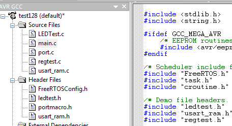
Until now, we used pretty simple program examples where all code fit into a single file and didn’t look very complicated. We didn’t care much about programming styles and modularizing. But due time, programs are going to grow bigger and more complex. It may become tough to maintain your code and even more complicated for other developers to read. We should follow some simple rules that make microcontroller programming more fun than scratching along. Split your programs Say you are writing a complex program that deals with LCD, USART, and even more peripherals. To make them all work, you need routines to init, read, write, and change mode. Imagine how many functions your single file would have to hold, and I am not talking about the main routine. It would end up with more scrolling than coding. So, the smart solution is to split your project into several files – libraries.

Continue reading

AVR Timer2 asynchronous mode

We have almost gone through main modes of AVR timers. It is impossible to review them all in more detail as there are lots of unique uses and cases. Anyway we will get back to them in future, as lots of routines are usually based on timer operations. We haven’t touched Timer/Counter2, which is another 8-bit timer of Atmega328. This is very similar to Timer0 with all pretty same features, including CTC, fast PWM and correct phase PWM modes. If you can run these modes in Timer0 then this will be easy doing on Timer2. The only difference is the naming of registers. So let’s leave this behind and get to something new and untouched. As I mentioned before, each timer has something unique, making them useful on special occasions. So this one isn’t an exception. It has a particular asynchronous timing mode which can be set to count events from an external clock source or be clocked with 32.768kHz crystal.

Continue reading

Programming 16 bit timer on Atmega328

Atmega328 has one 16 bit timer, which is more powerful comparing to 8-bit timers. A 16-bit timer is called Timer/Counter1. Counter1 has twice more bits than 8-bit Counter0, so you get more counts leading to longer duration and more precise timings. The 16-bit timer has the same functionality as Timer0 plus more specific ones. We won’t be discussing Normal, CTC, fast PWM, and correct phase PWM modes, as these are equivalent to Timer0. But let’s focus on new things. There we have a new module called Input Capture Unit along with Input Capture Flag (ICF1) interrupt and the original waveform generating mode called Phase and Frequency Correct PWM.

Continue reading

8-bit Timer/Counter0 operation modes. Part2

Previously we have revealed only two Timer/Counter0 modes: Normal and CTC. So far, there are a couple more helpful working modes, Fast PWM and Phase Correct PWM. These modes are even more complicated compared to what we know. But let’s not get scared of this and go through these modes step by step. First of all, let’s remember the basics of what PWM is and then do some practical stuff. Short intro to PWM Pulse Width Modulation (PWM) is a widely used technique for digitally controlling analog circuits. When talking analog circuits – these include lamps, motors, power converters, and more. For instance, simple DC motor speed can be adjusted by varying a supply voltage. But imagine what circuitry would be to do this through the microcontroller. To make things simpler, a PWM method was introduced. This allows controlling analog circuits digitally without high cost and complexity. Simply speaking, PWM is a way of encoding analog signal levels. We know that microcontrollers are excellent at creating square waves. So the only thing has to be taken care of – switching…

Continue reading

8-bit Timer/Counter0 operation modes.Part1

As our selected Atmega328 microcontroller has three timers, I think it is best to analyze them separately. Timer/Counter0 is probably mainly used the timer in various applications. It is capable of operating as a simple counter, frequency generator including PWM, and external source clock counter and can generate tree interrupts: one overflow (TOV0) and two independent output compare match interrupts (OCF0A and OCF0B). As you see Timer/Counter0 register, TCN0 has two 8 bit double buffered Output Compare Registers (OCR0A and OCR0B) associated that can be used to generate two different waveforms on microcontroller pins OC0A and OC0B and two interrupts (OCF0A and OCF0B) as well. Each timer interrupt can be enabled individually in TIMSK0 register by setting bits to one. TIFR0 register holds bits indicating interrupt request signals. And, of course, there are two more essential registers, TCCR0A and TCCR0B. These are used to set timer operation modes, set prescallers, and start timer itself. It would take lots of space to go into details describing these registers – besides, all info is nicely plotted in datasheets. Better focus on some…

Continue reading

AVR timers do more than count time

Timers/Counters are probably one of the most complex peripherals in microcontrollers, but they are most common no matter what complexity the program is. Designers of timers have put a lot of thought into them, making them very flexible and versatile for all timing-dependent tasks like measuring periods, generating PWM signals, generating output signals, and timed interrupts. Timers run independently from the AVR core. Once set, they do their silent job while AVR can do other tasks or go to sleep. AVR can read timer values or change operation modes whenever it needs or only can be interrupted with several available interrupts. If you see an application where the frequency is measured, music is generated, or motor is driven, a timer is involved.

Continue reading