Microcontrollers are meant to deal with digital information. They only understand ‘0’ and ‘1’ values. So what if we need to get some non-digital data into the microcontroller. The only way is to digitize or, to speak convert analog into digital. This is why almost all microcontrollers are featured with the ADC module. Among other electronic parts, the Atmega328 microcontroller also has 8 (or 6 in the PDIP package) ADC input channels.
All these can be used to read an analog value that is within the reference voltage range.
Let us see how this is easy.
Operation Modes of ADC in ATmega328
First of all, we need to keep in mind that the internal ADC module in any microcontroller doesn’t pretend to be the best choice in all applications. It is meant to be used in relatively slow and not extremely accurate data acquisitions. Anyway, this is an excellent choice in most situations, like reading sensor data or reading waveforms.
AVR ADC module has a 10-bit resolution with +/-2LSB accuracy. It can convert data at up to 76.9kSPS, which goes down when a higher resolution is used. We mentioned that there are 8 ADC channels available on pins, but three internal channels can be selected with the multiplexer decoder. These are temperature sensors (channel 8), bandgap reference (1.1V), and GND (0V).
These specific channels may be handy in various situations. The temperature sensor is no doubt useful in many cases. Bandgap voltage source remains constant when VCC varies, so it can be used to read the supply voltage level itself (as we will see later).
ADC can be set up for free running conversion, single conversion, and interrupt-based conversion. Let us see how a single conversion can be done by analyzing the following example.
ADC Single conversion mode
Before writing the analog to a digital conversion program, we need to take care of the AVR chip’s analog part. This includes powering analog peripherals by applying the voltage to AVCC, setting a reference voltage level in the AREF pin, and ensuring some protection from supply noise using a low pass filter.
For simple applications, the datasheet recommends adding a 100nF capacitor and 10uH inductor to the AVCC pin that performs as a low pass filter.
In our example, we set the reference voltage to the same as the power supply voltage. So we need to connect the AREF pin to the AVCC source. If we used an internal 1.1V reference voltage, we would have to connect a capacitor between the VREF pin and GND to reduce the chance of noise.
In our example, we are going to measure a potentiometer value, bang gap voltage, and send data via USART. The potentiometer is connected to the ADC0 channel.
Initialization of ADC
To start using ADC we need to initialize it first. For this, we write a simple function:
void InitADC()
{
 // Select Vref=AVcc
 ADMUX |= (1<<REFS0);
 //set prescaller to 128 and enable ADC
 ADCSRA |= (1<<ADPS2)|(1<<ADPS1)|(1<<ADPS0)|(1<<ADEN);
}
As we can see, first of all, we have to select the reference voltage source by setting REFS0 fuze in the ADMUX register. As the datasheet says, AREF is connected to AVCC, and we only need to connect a capacitor between the AREF pin and the ground.
AVR ADC must be clocked at a frequency between 50 and 200kHz. So we need to set proper prescaller bits so that the scaled system clock would fit in this range. As our AVR is clocked at 16MHz, we will use 128 scaling factors by setting ADPS0, ADPS1, and ADPS2 bits in the ADCSRA register. This gives 16000000/128=125kHz of ADC clock.
And lastly, we enable the ADC module by setting ADEN bit in the ADCSRA register.
ADC conversion
Now ADC is set and turned. We can start conversion. For this, we prepare the following function that reads the ADC value from the selected channel and returns a 16-bit value:
uint16_t ReadADC(uint8_t ADCchannel)
{
 //select ADC channel with safety mask
 ADMUX = (ADMUX & 0xF0) | (ADCchannel & 0x0F);
 //single conversion mode
 ADCSRA |= (1<<ADSC);
 // wait until ADC conversion is complete
 while( ADCSRA & (1<<ADSC) );
 return ADC;
}
before deciding the ADC channel in the ADMUX register, we use a mask (0b00001111) which protects from an unintentional alteration of the ADMUX register.
After the channel is selected, we start a single conversion by setting the ADSC bit in the ADCSRA register. This bit remains high until the conversion is complete. So we are going to use this bit as an indicator to decide when data is ready. So we return the ADC value after the ADSC bit is reset.
Full source code
This is all we need. Here is a complete code that reads the potentiometer value and Vbg voltage that is sent to the USART terminal:
#include <stdio.h>
#include <avr/io.h>
#include <util/delay.h>
#define USART_BAUDRATE 9600
#define UBRR_VALUE (((F_CPU / (USART_BAUDRATE * 16UL))) - 1)
#define VREF 5
#define POT 10000
void USART0Init(void)
{
// Set baud rate
UBRR0H = (uint8_t)(UBRR_VALUE>>8);
UBRR0L = (uint8_t)UBRR_VALUE;
// Set frame format to 8 data bits, no parity, 1 stop bit
UCSR0C |= (1<<UCSZ01)|(1<<UCSZ00);
//enable transmission and reception
UCSR0B |= (1<<RXEN0)|(1<<TXEN0);
}
int USART0SendByte(char u8Data, FILE *stream)
{
   if(u8Data == '\n')
   {
        USART0SendByte('\r', stream);
   }
//wait while previous byte is completed
while(!(UCSR0A&(1<<UDRE0))){};
// Transmit data
UDR0 = u8Data;
return 0;
}
//set stream pointer
FILE usart0_str = FDEV_SETUP_STREAM(USART0SendByte, NULL, _FDEV_SETUP_WRITE);
void InitADC()
{
    // Select Vref=AVcc
    ADMUX |= (1<<REFS0);
    //set prescaller to 128 and enable ADC
    ADCSRA |= (1<<ADPS2)|(1<<ADPS1)|(1<<ADPS0)|(1<<ADEN);
}
uint16_t ReadADC(uint8_t ADCchannel)
{
    //select ADC channel with safety mask
    ADMUX = (ADMUX & 0xF0) | (ADCchannel & 0x0F);
    //single conversion mode
    ADCSRA |= (1<<ADSC);
    // wait until ADC conversion is complete
    while( ADCSRA & (1<<ADSC) );
   return ADC;
}
int main()
{
double vbg, potval;
//initialize ADC
InitADC();
//Initialize USART0
USART0Init();
//assign our stream to standart I/O streams
stdout=&usart0_str;
while(1)
{
    //reading potentiometer value and recalculating to Ohms
    potval=(double)POT/1024*ReadADC(0);
    //sending potentiometer avlue to terminal
    printf("Potentiometer value = %u Ohm\n", (uint16_t)potval);
    //reading band gap voltage and recalculating to volts
    vbg=(double)VREF/1024*ReadADC(14);
    //printing value to terminal
    printf("Vbg = %4.2fV\n", vbg);
    //approximate 1s
    _delay_ms(1000);
}
}
ADC conversion results
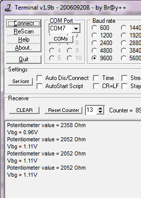
After reset, we get a Vbg value of 0.96 and then a steady 1.11V. This is because bandgap voltage (also internal reference) needs time to stabilize after being switched on. So it is best practice to discard first readings as they may be inaccurate. The datasheet mentions that bandgap voltage is near 1.1V we get 1.11 – this is close enough. In the next tutorial part, we will discuss using Interrupt to detect complete conversion and automatic triggering of ADC conversions.
Download project files: readADC.zip


A few comments:
1. There is no need to set ADEN last. You can set all of ADCSRA at the same time.
2.ReadADC() is flawed in that if you call ReadADC(1) then ReadADC(2) you will actually convert channel 3. I would do this:
ADMUX = (ADMUX & 0xF0) | (ADCchannel & 0x0F);
3. USART0SendByte()
Why the bizarre recursive calling? Why not simply re-write the value of u8Data?
Another one I noticed:
potval=(uint16_t)(POT/1024*ReadADC(0));
This actually compiles to potval = 9 * ReadADC(0);
This is because POT/1024 is computed as 9, leading to a fairly large error. You should either do ((ReadADC(0) * POT) / 1024) using 32bit ints, or since you have some floating point already, just use that.
Hi DT,
Thank you for checking things out.
1. I just left it for tutorial purposes. But actually this doesn’t make sense, so fixed according to your comments.
2. Fixed.
3. I use recursive function to make things simpler. Instead of writing printf(“\r\n”); i have to write printf(“\n”); Rewriting ‘\n’ with ‘\r’ would give different view in terminal window.
4. Fixed potentiometer value calculation.
RE: 3
I see what you are doing but I’d hardly call it simpler than just using “\n\r”. Its certainly less portable, since it assumes you only want to send ASCII data. If “\n\r” this leads to extra RAM usage, then use printf_P(). I’d also argue that recursion is not a practice to encourage on embedded systems.
Another note: the float format string %1.2f doesn’t make much sense. The 1 refers to the total field width, but this has to be ignored since to do so the function wouldn’t be able to fulfil the “.2” bit. In this case (if I understood your intent) “%4.2f” makes more sense i.e 1 ‘units’ digit, the decimal point, plus 2 fractional digits totalling a width of 4.
I agree with you about recursions. Will avoid this in future tutorials.
And yes I was a bit inertial with float format string. Somehow I made it look like what I wanted to see. Fixed. Thanks.
vbg=(double)VREF/1024*ReadADC(14); – is that correct?? ReadADC(14)? not ReadADC(30)?
Am I right that this references to Table 22-4. Input Channel and Gain Selections of the datasheet?
Why the mask if 0f and f0? it seems DT made a mistake, it should read 1f and e0 instead! please, check the datasheet and explain, what’s going on. it’s difficult to understand. what was the initial version?
Thanks
Hi, I’m new to c programming and embedded systems. I tried to run your program on my mac but this is the error I get:
prueba.c: In function ‘USART0SendByte’:
prueba.c:22:1: error: stray ‘\302’ in program
prueba.c:22:1: error: stray ‘\240’ in program
prueba.c:23:1: error: stray ‘\302’ in program
prueba.c:23:1: error: stray ‘\240’ in program
prueba.c:24:1: error: stray ‘\302’ in program
prueba.c:24:1: error: stray ‘\240’ in program
prueba.c:25:1: error: stray ‘\302’ in program
prueba.c:25:1: error: stray ‘\240’ in program
prueba.c: At top level:
In line 22 I have
if(u8Data == ‘\n’)
I hope you can help me thanks!
Could be that you have wrong characters due to copied code from website. I have attached project files at the end of post.
I have observed that in the world these days, video games include the latest popularity with kids of all ages. Periodically it may be extremely hard to drag the kids away from the games. If you want the best of both worlds, there are plenty of educational games for kids. Great post. babeagcegfcbgdka