Using Direct Memory Access (DMA) in STM32 projects

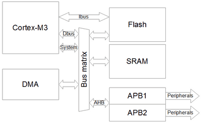
In many microcontroller projects, you need to read and write data. It can read data from the peripheral unit like ADC and write values to RAM. In another case, maybe you need to send chunks of data using SPI. Again you need to read it from RAM and continuously write to the SPI data register. When you do this using processor – you lose a significant amount of processing time. Most advanced microcontrollers have a Direct Memory Access (DMA) controller to avoid occupying the CPU. As its name says – DMA does data transfers between memory locations without the need for a CPU. Low and medium-density ST32 microcontrollers have a single 7-channel DMA unit, while high-density devices have two DMA controllers with 12 independent channels. In STM32VLDiscovery, their ST32F100RB microcontroller with a single DMA unit having 7 channels.

Continue reading

Multichannel ADC using DMA on STM32

Previously we have tried to do a single conversion of one ADC channel. We were waiting for the ADC result in a loop, which isn’t an effective way of using processor resources. It is better to trigger a conversion and wait for the conversion to complete the interrupt. This way, a processor can do other tasks rather than wait for ADC conversion to complete. This time we will go through another example to set up more than one channel and read ADC values using interrupt service routine. How does multichannel ADC conversion works? If we need to convert several channels continuously, we need to set up Sequence registers (ADC_SQRx). There are three sequence registers: ADC_SQR1, ADC_SQR2, and ADC_SQR3 where we can set up a maximum of 16 channels in any order. Conversion sequence starts with SQ1[4:0] settings in ADC_SQR3 register. Bits [4:0] hold the number of ADC channels.

Continue reading

Use fixed integer types to enhance portability

If you have programmed anything with C, you should be familiar with common data types like char, unsigned char, int, unsigned int, long int, long long int, etc. It is tough to tell by the looks of the type how many bytes this variable takes on memory and how it looks in a different system. For instance, in 8-bit AVR-GCC compiler, int is a 16-bit type, while in ARM-GCC, int is 32-bit. So int size is dependent on platform, compiler, and runtime libraries. And switching between systems may trick you if you are not careful enough. You can always check the size of the variable by using sizeof() function. What to do if you need your code to be portable between different systems. Some great libraries could work on any system, including 8-bit, 16-bit, 32-bit, or 64-bit. To avoid this annoying problem, the ISO C99 standard introduced portable data types that are defined in stdint.h header file. If you open this header file of your default compiler tool-set you will find how things are organized. First of all, it checks…

Continue reading

Introducing to STM32 ADC programming. Part2

After we had a quick overview of the STM32 ADC peripheral, we can dig deeper into specifics. To understand simple things, let’s go with the simplest case – single conversion mode. In this mode, ADC does one conversion and then stops. After the ADC conversion result is stored into the 16-bit ADC_DR data register (remember that the conversion result is 12-bit), then the End of Conversion (EOC) flag is set. An interrupt is generated if the EOCIE flag is set. The same situation is if the injected channel is converted. The difference is that the result is stored in the corresponding ADC_DRJx register, the JEOC flag is set, an interrupt is generated if the JEOCIE flag is set. In our example, we will measure the internal temperature sensor value and send it using USART. A temperature sensor is internally connected to the ADC1_IN16 channel. The algorithm will start a single conversion and wait for the conversion complete flag EOC. We will then read the ADC value from the ADC_DR register, which will later be used to calculate Celsius’s temperature value…

Continue reading

Introducing to STM32 ADC programming. Part1

STM32 ADC is a pretty complex peripheral. It is designed to be flexible enough to accomplish complex tasks. We will dedicate a few posts where we will try to cover the main features and give working examples of code. The block schematic may look scary the first time, but it can be split into several pieces that are responsible for different functions if you look closer. Will will go through them step by step to make it look brighter.

Continue reading

Programming STM32 USART using GCC tools. Part 2

In the last part of the tutorial, we have covered simple USART routines that send data directly to USART peripheral. This is OK to use such an approach when a project isn’t time-critical and processing resources are far from limits. But most often, we stuck with these limiting factors, mainly when RTOS is used or when we perform necessary real-time data processing. And having USART routines with while the loop-based wait isn’t a good idea – it steals processing power only to send a data. As you may guess – next step is to employ interrupts. As you can see, there are many sources to trigger interrupts, and each of them is used for a different purpose. To use one or another interrupt, first, it has to be enabled in USART control register (USART_CR1, USART_CR2, or USART_CR3). Then NVIC USART_IRQn channel has to be enabled to map interrupt to its service routine. Because NVIC has only one vector for all USART interrupt triggers, service routine has to figure out which of interrupts has triggered an event. This is done by…

Continue reading