Programming AVR I2C interface
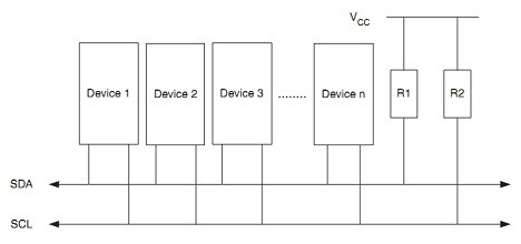
I2C (also referred as IIC or TWI) is widely used interface in embedded applications. Two wire bus initially was used by Philips and become a standard among chip vendors. I2C bus consists of two lines called Serial Data Line (SDA) and Serial Clock Line (SCL). Communication is relatively fast and short distance mainly used to communicate between sensors, RTC, EEPROM, LCD. I2C protocol allows up to 128 devices connected to those two lines where each of them has unique address. Communication between devices is master and slave based. Master generates clock signal, initiates and terminates data transfer.

From electrical point of view I2C devices use open drain (open collector) pins. In order to operate correctly SDA and SCL lines require pull up resistors. Typically 4.7kΩ resistors are used. Read more »

Serial peripheral interface in AVR microcontrollers

Serial Peripheral Interface (SPI) is fastest synchronous communication interface allowing data transfer speeds up to half of core clock. If AVR microcontroller is clocked at 16MHz then SPI clock may reach 8MHz in master mode. SPI communication interface is common way to talk to other peripherals around MCU like flash, EEPROM, sensors and even other microcontrollers.

Generally speaking devices communicate over SPI interface using four wires MISO (Master In Slave out), MOSI (Master Out Slave In), SCK (synchronization clock) and SS (Slave Select). Usually if only one slave device is used SS line is omitted while slave chip select pin is tied to ground. How ever this is a special case in all other cases SS pin has to be controlled manually in software – this isn’t handled automatically. If more slaves are connected to SPI interface there are options in selecting right slave device: one is to use dedicated SS pins for each slave or if slave supports this use address bytes in data packets to select one (for instance in MCP23S17 I/O expanders). Read more »

ADC on Atmega328. Part 2

After we’ve learned how to performs simple ADC conversions on AVR microcontroller we can move forward with more complex tasks. AVR ADC module has many useful features that make conversions more robust without occupying MCU resources.

Imagine that we need to sample analog waveform or audio signal. It has to be done precisely at defined sampling frequency like 20kHz. The only way to do this correct is to use auto-triggering with exact time intervals. Why not to pass counting task to timer? Lets write Timer0 auto triggered ADC conversions with ADC complete interrupt service routine. Read more »

ADC on Atmega328. Part 1

Microcontrollers are meant to deal with digital information. They only understant ’0′ and ’1′ values. So what if we need to get some non digital data in to microcontroller. The only way is to digitize or simply speaking to convert analog in to digital. This is why almost all microcontrollers are featured with ADC module. Atmega328 microcontroller also have 8 (or 6 in PDIP package) ADC input channels.

All these can be used to read any analog value that is within reference voltage range.

Lets see how this is easy. Read more »

Next Page »