In this tutorial, we will be interfacing an HD44780 character LCD. Although as an alternative, you can use JHD162A LCD. Both follow the same instruction set along with the same pin diagram. Both these LCDs are readily available in the market at a low cost. HD44780 LCD has a set of 16 columns and two rows for display.

The pin diagram of the LCD is as follows

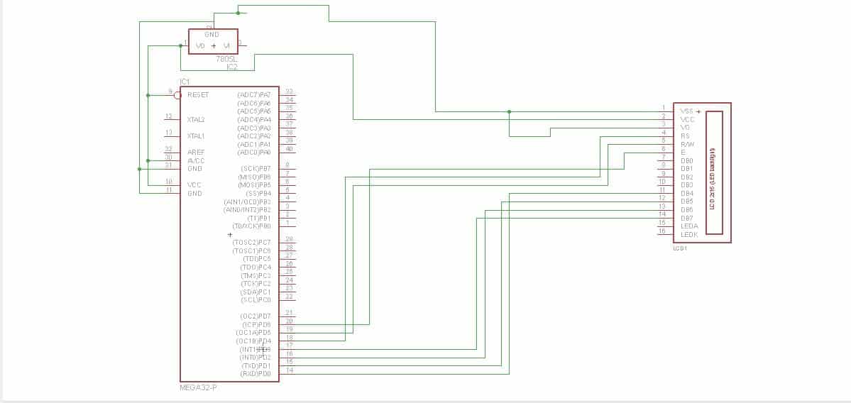
There are two ways to interface an LCD. One way is the 8-bit mode which requires 11 pins, and the other methods are the 4-bit mode which requires only seven pins. The 8-bit mode is faster than 4-bit mode, but one has to compromise in the number of pins available for other operations. The pins 15 and 16 are used for back-light display. Pin15 has to be connected to a positive supply while pin 16 to negative.
In this tutorial, we will be using the display in 4-bit mode. Also, we won’t get into details of how the LCD work and what is its instruction sets. We will be using a library for interfacing LCD as it will be time-saving, efficient, and easy-to learn to. Download the library from here [LCd_library]. Before moving to the coding part, we will first configure the library.
Adding And Configuring The Library
Before starting configuration of the library, make sure you have created a new project. I will be using AVR studio 5, but the procedure remains the same for any other compiler. Please follow the illustrations given below

Right clock on your project name in the solution-explorer windows and navigate to ‘existing item’ as shown above.
Now browse to the downloaded library files and add both lcd.h as well as lcd.c
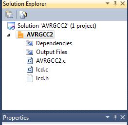
After adding the solution explorer window should look like this
Now double-click on the lcd.h file in the solution explorer windows. As soon as you do that, you will find lcd.h open up right next to your project file.c window, just like tabs in any internet browser
Here comes the main part of configuring the library. Scroll down very slowly until you find the following “ #define XTAL 1000000.”

The above line is responsible for calculating the delay in LCD operation. Here, you have to define your crystal frequency irrespective of whether you are using an internal or external clock. Currently, it’s set to 1MHZ. To change it to 12MHZ, replace 1000000 by 12000000.
Scroll down until you find the following
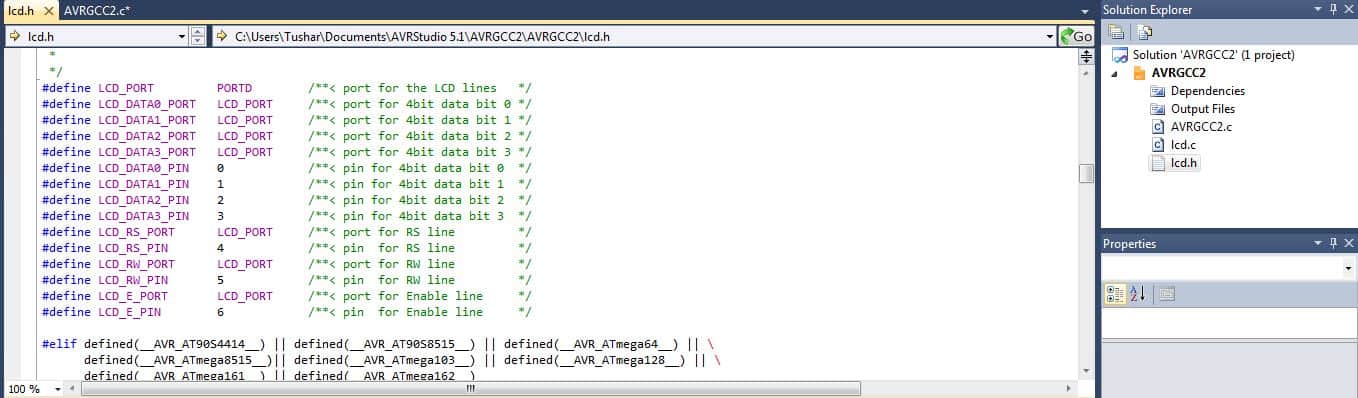
As you can see, the above set of liens is responsible for selecting a port to interface with the LCD. Currently, it’s set to PORTD. If you want to use any other port like PORTB, you can change PORTD to PORTB. As you continue to scroll down, you can find the list of functions that can be used, like lcdgotoxy(x,y), lcd_home() that can be used directly in your code.
Full Sourcecode
#include <avr/io.h>
#include <util/delay.h>

#include "lcd.h"

int main(void)
{
    lcd_init(LCD_DISP_ON); /* initialize lcd, display on */
    lcd_clrscr();             /* clear screen of lcd */

    while(1)                      /* infinite loop */
    {

        lcd_home();               /* bring cursor to 0,0 */
        lcd_puts("Welcome");      /*text to be displayed */
        lcd_gotoxy(8,1);          /* go to 2nd row 8th col */
        lcd_puts("To Embedds.com");  /* text to be displayed */
        _delay_ms(100);            /* wait 100ms */
    }
}
Explanation:
Initially, the LCD is initialized to cursor off and display on command lcd_init(LCD_DIsply_ON). However, if you want blinking cursor, you can replace the initialization with lcd_init(LCD_DISPLAY_ON_CURSOR_BLINK). More sets of initialization options can be found in the library configuration, as mentioned above. The next step clears everything written on lcd, and then the code is self-explanatory. However, the procedure to display numbers, both integer and floating, is different.
Displaying Numbers on the lcd
Currently, the library doesn’t support displaying numbers, both integer and floating point. However, there is a workaround for this. For displaying integer values, the following things are to be added up

By declaring an ‘a’ character array and using the itoa() function, we are converting the number into equivalent characters with the name ‘a’ and then displaying “a.”
For displaying floating values, the following changes are required

Make sure in both cases; you include the delay and the LCD library. Also, even if the code gets compiled, in the floating cases, you might get a “?” mark. To solve you can navigate here and follow the steps. They worked for me.
By: Tushar Gupta
When using 4bit operation… connect pin 1,3,5,7,8,9,and 10 to GND… You only need 6 signals to drive LCD…Pin 3 to GND will set highest contrast setting…
yes you are right setting 3 pin to ground will set to high contrast and regarding 5 pin you can set it to low,till you are writing the data,but it won’t save you any pin as the library is configured to use that pin and you can’t use it for any other purpose. Also even if you are not using the library and using the general method by giving commands,you need to connect the read/write pin as before writing any data you have to check whether the lcd is busy or not.To check first you have to set high the read/write pin and then monitor the d7 bit until it goes low. Alternate way is to give a delay before writing the next data. Also regarding the 4 data pins 7,8,9,10 it’s not a necessary to connect them to ground.You can connect them if your display is not properly displaying the reuqired daya ,inspite of correct code. The lCd works for me by leaving these four pins unconnected
By the way,thanks for reading the blog.If still you have any doubt you can comment below or even you can mail me at bondtushar@gmail.com .i will try to reply to your mail within 12 hours
sir i want some lpc2148 projects. i want to learn.help me
here is a good example of LPC2148:
http://www.scienceprog.com/driving-leds-with-lpc2148-microcontroller/
Thanks for the great library! I’ve tried many that ended in fail but your diagram and example code was a success.
Have you tried a 16×1 display instead of a 16×2? My 16×1 works but only prints on the first half of the screen.