After we had a quick overview of the STM32 ADC peripheral, we can dig deeper into specifics. To understand simple things, let’s go with the simplest case – single conversion mode. In this mode, ADC does one conversion and then stops. After the ADC conversion result is stored into the 16-bit ADC_DR data register (remember that the conversion result is 12-bit), then the End of Conversion (EOC) flag is set. An interrupt is generated if the EOCIE flag is set. The same situation is if the injected channel is converted. The difference is that the result is stored in the corresponding ADC_DRJx register, the JEOC flag is set, an interrupt is generated if the JEOCIE flag is set.
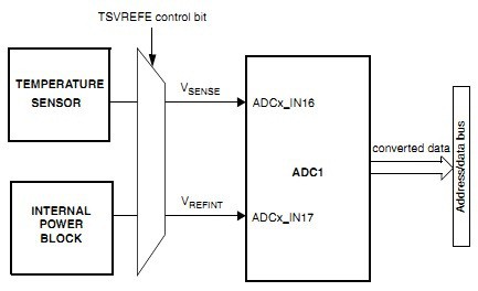
In our example, we will measure the internal temperature sensor value and send it using USART. A temperature sensor is internally connected to the ADC1_IN16 channel. The algorithm will start a single conversion and wait for the conversion complete flag EOC. We will then read the ADC value from the ADC_DR register, which will later be used to calculate Celsius’s temperature value and sent via USART. So we should see value in the terminal screen. As usual, we are going to use the Standard peripheral library and CMSIS functions. The code for the single conversion is pretty short:
#include "stm32f10x.h"
#include "usart.h"
#include <stdio.h>
uint16_t AD_value;
const uint16_t V25 = 1750;// when V25=1.41V at ref 3.3V
const uint16_t Avg_Slope = 5; //when avg_slope=4.3mV/C at ref 3.3V
uint16_t TemperatureC;
int main(void)
{
//initialize USART1
Usart1Init();
//enable ADC1 clock
RCC_APB2PeriphClockCmd(RCC_APB2Periph_ADC1, ENABLE);
ADC_InitTypeDef ADC_InitStructure;
//ADC1 configuration
//select independent conversion mode (single)
ADC_InitStructure.ADC_Mode = ADC_Mode_Independent;
//We will convert single channel only
ADC_InitStructure.ADC_ScanConvMode = DISABLE;
//we will convert one time
ADC_InitStructure.ADC_ContinuousConvMode = DISABLE;
//select no external triggering
ADC_InitStructure.ADC_ExternalTrigConv = ADC_ExternalTrigConv_None;
//right 12-bit data alignment in ADC data register
ADC_InitStructure.ADC_DataAlign = ADC_DataAlign_Right;
//single channel conversion
ADC_InitStructure.ADC_NbrOfChannel = 1;
//load structure values to control and status registers
ADC_Init(ADC1, &ADC_InitStructure);
//wake up temperature sensor
ADC_TempSensorVrefintCmd(ENABLE);
//ADC1 channel16 configuration
//we select 41.5 cycles conversion for channel16
//and rank=1 which doesn't matter in single mode
ADC_RegularChannelConfig(ADC1, ADC_Channel_16, 1, ADC_SampleTime_41Cycles5);
//Enable ADC1
ADC_Cmd(ADC1, ENABLE);
//Enable ADC1 reset calibration register
ADC_ResetCalibration(ADC1);
//Check the end of ADC1 reset calibration register
while(ADC_GetResetCalibrationStatus(ADC1));
//Start ADC1 calibration
ADC_StartCalibration(ADC1);
//Check the end of ADC1 calibration
while(ADC_GetCalibrationStatus(ADC1));
//Start ADC1 Software Conversion
ADC_SoftwareStartConvCmd(ADC1, ENABLE);
//wait for conversion complete
while(!ADC_GetFlagStatus(ADC1, ADC_FLAG_EOC)){}
//read ADC value
AD_value=ADC_GetConversionValue(ADC1);
//clear EOC flag
ADC_ClearFlag(ADC1, ADC_FLAG_EOC);
printf("\r\n ADC value: %d \r\n", AD_value);
TemperatureC = (uint16_t)((V25-AD_value)/Avg_Slope+25);
printf("Temperature: %d%cC\r\n", TemperatureC, 176);
while (1)
  {
    //interrupts does the job
  }
}
When standard peripheral functions are used, everything becomes simple. First, we set enable ADC peripheral clock:
RCC_APB2PeriphClockCmd(RCC_APB2Periph_ADC1, ENABLE);
It is connected to the APB2 bus. We aren’t using any prescallers here, so it works at 24MHz here.
The next thing is to set up ADC mode using ADC_initstructure. Here we select ADC_Mode_Independent, which in our case is single conversion. Then we disable scan mode and continuous scan as we want only a single conversion and stop. We also disable any external triggering and select data to be right-aligned. To access the temperature sensor, we need to bring it from the power-down by writing the TSVREFE bit in the ADC_CR2 register. This is done by using the command:
ADC_TempSensorVrefintCmd(ENABLE);
After ADC is set up and the sensor is woken, we can configure channel 16. Here we need to set several parameters, including channel number, the index in the group, and channel sampling time:
ADC_RegularChannelConfig(ADC1, ADC_Channel_16, 1, ADC_SampleTime_41Cycles5);
Then we enable ADC:
ADC_Cmd(ADC1, ENABLE);
After the microcontroller is powered on, it is recommended to run ADC self-calibration. This calculates error correction codes for capacitors and reduces overall error in the result.
//Enable ADC1 reset calibration register
ADC_ResetCalibration(ADC1);
//Check the end of ADC1 reset calibration register
while(ADC_GetResetCalibrationStatus(ADC1));
//Start ADC1 calibration
ADC_StartCalibration(ADC1);
//Check the end of ADC1 calibration
while(ADC_GetCalibrationStatus(ADC1));
Now its time to start conversion. The function for this is:
ADC_SoftwareStartConvCmd(ADC1, ENABLE);
The next thing is to wait for the conversion to complete by checking for the ADC_FLAG_EOC flag in the status register:
while(!ADC_GetFlagStatus(ADC1, ADC_FLAG_EOC)){}
Then we can take ADC value from the data register:
AD_value=ADC_GetConversionValue(ADC1);
After reading the temperature sensor, we get some 12-bit digital values. To calculate temperature, we need to use a formula:
Temperature = (V25-AD_value)/Avg_slope+25
V25 and Avg_slope values can be found on microcontroller datasheet:
Here we get that V25 is typically 1.41V and Avg_Slope=4.3. When using 3.3V supply as a reference, we get approximately V25=1750 and Avg_Slope=5. Having these temperature value can be easily calculated:
TemperatureC = (uint16_t)((V25-AD_value)/Avg_Slope+25);
Please don’t rely on readings as the manufacturer states it can vary from chip to chip up to 45ºC. It can serve only to detect temperature variations inside the chip. It is always better to use an external sensor for accurate readings.
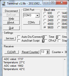
This is how data looks on the terminal screen. The first read ls room temperature, and the second is with some heat applied to the microcontroller:
This code is only to demonstrate the most straightforward ADC usage. Practically it is Very inefficient because there are loops used for waiting for ADC to be complete. There are better ways of doing this, like using interrupts or DMA. Next time we will try different ADC mode used more efficiently.
The example source code is here: STM32DiscoveryADCSingle.zip


you are writing
“Here we get that V25 is typically 1.41V and Avg_Slope=4.3. When using 3.3V supply as reference we get approximately V25=1750”
how did you get 1750? thx
These are ADC values of voltages taken from datasheet:
VCC and VREF = 3.3V; ADC_value = 4096
V25 = 1.41V; ADC_Value=1750 (calculated = (1.41/3.3)*4096)
Avg_Slope = 4.3mV ADC_value=5 (calculated = (0.0043/3.3)*4096)
Please tell me how to calculate sample time that is given 41 cycle in the code.
Excellent explanations, thanks a lot!
How to find out on which channel was made last conversion. Could you make some example of basic multi channel conversion, where every channel has another function (meaning of different source) and where will be seems how to get these different values without DMA?
To AAA, sample time is selected in ADC_SMPR1 and ADC_SMPR2 registers. You can find this in datasheet.
MartinP, you should keep track of different channel conversions.
Where is it stated that the temp sensor is connected to ADC1_IN16 ? In DS (CD00161566.pdf) on page 20 it is written that temp sensor is connected to ADC12_IN16. But there is no ADC12, right? I am confused now. Could you please explain it?
And I tried your code it works but I am getting 433 as adc result and 288 as temperatur. Ohh, maybe because of the clock settings? I have 8MHz external xtal and CPU runs at 72 MHz. What shall I do?
Thanks.
Temperature sensor in STM32 is internally connected to ADC1_IN16 channel. Probably there is an error in document where you found ADC12_IN16.
If you read 433 ADC value, your temperature should be ~45C.
For more detailed info take a look at reference manual (http://www.st.com/st-web-ui/static/active/en/resource/technical/document/reference_manual/CD00246267.pdf), not datasheet.
@MUBIN re ADC12_IN16 I believe Both ADC1 and ADC2 both share channel 16, the ref man labels it ADC12_XXX. Someone correct me if I’m wrong.
It appears to be so. Also channel 17 (VREFINT). If there is an ADC3 – same applies to it too.
Hello every body …This is pavan i need to write a adc programming for multichannel on STM32F0.
Please provide source code for this one.
Trying this code I get 1947 ADC code. What is the normal values that I must read? What should be the Temp with this reading – 65 degrees?
On which pin of microcontroller STM32F407VGT6, ADC1_IN16 (Temperature Channel) channel is located?
sir,,please suggest a good book for programming STM32F103C8T6 in Embedded-c …please sir help me