In this tutorial, we will see a practical way of coding interrupts. Our task for today will be to learn interrupts for GPIO and Timers. In the initial part, we will first look at coding interrupts for the GPIO pins, and in the other half, we will modify this code to add interrupts for timers. By the end of the tutorial, you will have a code that will blink a led using a timer interrupt. However, the blinking frequency will vary if you push a button.

In the last tutorial on timers, we saw that we were continuously monitoring the timer flag to check when the timer has overflown. This process is called polling. The only problem with this method is it keeps the processor busy. What if we had another way by which the timer would itself tell the CPU that the timer had overflown? This is where interrupts come into the picture. For example, imagine a scenario where you would always go up to the door to see someone s there or not. This process can be called polling—however, the door-bell act as an interrupt, which notifies us that there is someone at the door. The interrupts come in handy when you want your microcontroller to do a task based on external circuitry’s response.
Every controller has an interrupt handling procedure so that it can encounter multiple sources/interrupts. The process for the MSP430 is also similar and is as follows:
- Completes the currently executing instruction.
- Pushing the PC, program counter which points to the next instruction, onto the stack.
- Pushing the SR, status register, onto the stack.
- Selects the highest priority interrupt if more than one is awaiting execution.
- The interrupt request flag resets automatically.
- The SR is cleared; this terminates any low-power mode; because the GIE (interrupt enable) bit is cleared, further interrupts are disabled.
- The interrupt vector content is loaded into the PC; the program continues with the interrupt service routine (ISR) at that address.
- On executing a return from an ISR, the SR and PC are popped from the stack, returning to run the instruction at the interrupt point.
- Because the SR is restored, interrupts are re-enabled.
Writing an interrupt service routine (ISR) varies from compiler to compiler but is very similar to writing encapsulated functions in C. The syntax is as follows:
#pragma vector = <VECTOR_NAME>
__interrupt void <ISR_NAME> (void) {
    //Your code goes here
}
Kindly note that there is no ‘;’ at the end of the pragma vector and interrupt code. The first line of the code tells the controller to be referenced for the particular interrupt named. The field vector name depends totally upon your interrupt part and is fixed for a device. For example, to code for GPIO, it’s called PORT1_VECTOR. Kindly note that this field varies from device to device, and you will have to refer either to the device header file or to its datasheet.
The other field ISR_NAME can be named anything. For example for port1, you can name it P1_ISR. It entirely depends upon you.
The next section follows the code or the action you want to perform after your interrupt has been answered.
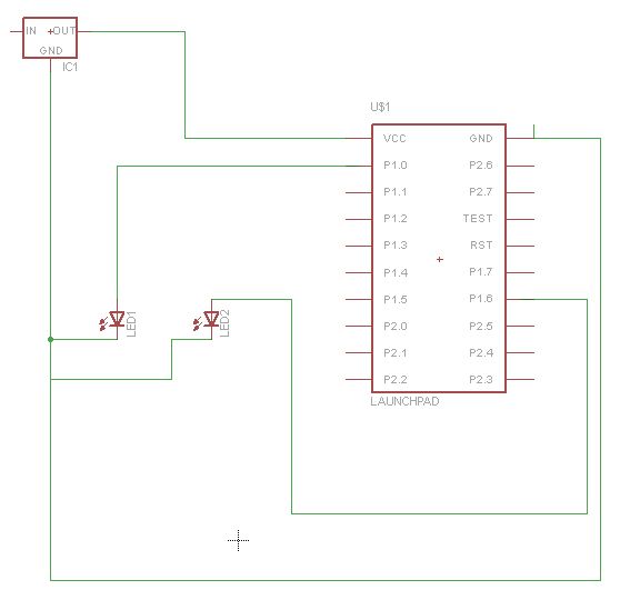
Let’s move onto the coding and the register part. A good thing about GPIO interrupt for msp430 is that it can be enabled on every single pin of each port. Since’ I am using Launchpad, the red led is connected to P1.1 while the button is P1.3. Remember that the default state of the button is high. We will require this fact in designing the interrupt. Three registers need to be configured for interrupt programming of GPIO.
The first register is PxIES, where x denoted the port. For port 1, this register will be called P1IES, and for port 2, it will be P2IES.
Each PxIES bit selects the interrupt edge for the corresponding I/O pin.
Bit = 0: The PxIFGx flag is set with a low-to-high transition
Bit = 1: The PxIFGx flag is set with a high-to-low transition
The thing with interrupts for GPIO is that they only get activated when there is a state change. The default state of the push-button is high. If you select a low to high transition, the interrupt will be activated after you have released a button after pushing it. However, for high-to-low transition, it will be activated as soon as you press the button. The advantage of using GPIO with the interrupt is you don’t need any delay to counter multiple key presses. We will be setting the bit high now, but I strongly recommend you also to set it low and see what the effect is.
Next register is the interrupt flag register (P1IFG, P2IFG)
This register only needs to be set to zero at the initialization part and once the interrupt gets called. This bit has to be cleared by the software. If you don’t do it, the interrupt will keep getting activated (without any button press) after the first button press.
Next register is PxIE(P1IE,P2IE)
This register enables the interrupt (i.e., we want to interrupt capability on this pin).
Since we are using, interrupt on p1.3, and we want to set it for the high-low transition. The register configuration will be as follows
P1IES |= 0x08;
P1IFG &= ~0x08;
P1IE |= 0x08;
You can see by setting P1IES as 0x08; it sets P1.3 as 1 for the P1IES register. I have used a bit-wise operator, and the register configuration is pretty understandable. However, if you still have any doubt, you can comment below.
One more thing is that the processor, however, isn’t set to recognize maskable interrupts like P1IFG. We can turn on the interrupts with:
_enable_interrupt();
This has to be done every time you are using interrupts
Here’s the code for GPIO interrupt, which enables the LED to press the button and switch it off when you again press the button. Kindly note that the flag has been cleared in the interrupt section.
#include <msp430g2553.h>
#define LED1  BIT0
int main(void) {
    WDTCTL = WDTPW | WDTHOLD;   // Stop watchdog timer
    BCSCTL1 = CALBC1_1MHZ;   //Set DCO to 1Mhz
    DCOCTL = CALDCO_1MHZ;
    P1OUT=0X00;
    P1DIR=0x01;   //P1.0 (LED) as output)

    P1IES |= 0x08;   // high -> low is selected with IESx = 1.
    P1IFG &= ~0x08;  // To prevent an immediate interrupt, clear the flag for
                         // P1.3 before enabling the interrupt.
    P1IE |= 0x08;    // Enable interrupts for P1.3
    _enable_interrupt();
    P1OUT |= 0x01;  //Initially the led will glow

    while(1)
    {
        }
    return 0;
}
#pragma vector = PORT1_VECTOR     //PORT1 interupt vecotr name
__interrupt void P1_ISR(void) {
             P1OUT ^= BIT0;
             P1IFG &= ~BIT3;           // clear the interupt flag
}
In the code, you will see that nothing has been mentioned in the while section. However, in projects, you will have some code running, but it will move to the interrupt vector and return when the ISR is finished as soon as the interrupt is there.
Next is the pretty easy timer interrupt. I recommend you to read the tutorial on a timer if you don’t have an idea. In this section, we will write a code that blinks the led; however, the led frequency changes back and forth between two pre-defined frequencies on the press of a button.
Everything remains pretty same for the timer except the introduction of one more register, which is the capture/compare control register. We will have a look at it when I introduce you to counters and PWM. As of now, you only have to set one bit in the register for enabling timer interrupt. If you refer to the datasheet BIT4 of the capture/compare control register (TACCTLx) is CCIE, i.e., capture compare interrupt enabled. When you set this bit too high, it allows the use of timer interrupt. Also, the vector name for timerA is ‘TIMER0_A0_VECTOR’, and you can give the ISR name of your choice.
One more thing about the timer interrupt is you don’t need to clear any flag when the interrupt is enabled. It gets automatically cleared, however for GPIO, and you have to clear it.
The code is given below
#include <msp430g2553.h>
#define LED1  BIT0
int main(void) {
    WDTCTL = WDTPW | WDTHOLD;   // Stop watchdog timer
    BCSCTL1 = CALBC1_1MHZ;   //Set DCO to 1Mhz
    DCOCTL = CALDCO_1MHZ;
    P1OUT=0X00;
    P1DIR=0x01;   //P1.0 (LED) as output)
    TACCR0 = 12499;  // time value
    TA0CTL |= TASSEL_2+ID_3+MC_1+TACLR; // using SMCLK with prescalr of 8 in upmode.
    TACCTL0 = CCIE;    //enable timer as interupts
    P1IES |= 0x08;   // high -> low is selected with IESx = 1.
    P1IFG &= ~0x08;  // To prevent an immediate interrupt, clear the flag for
                         // P1.3 before enabling the interrupt.
    P1IE |= 0x08;    // Enable interrupts for P1.3
    _enable_interrupt();
    P1OUT |= 0x01;  //Initially the led will glow

    while(1)
    {
        }
    return 0;
}
#pragma vector=TIMER0_A0_VECTOR   //Timera interrupt vector name
__interrupt void TIMER_A(void) {
    P1OUT ^= BIT0;           //compliment the state of led
}

#pragma vector = PORT1_VECTOR     //PORT1 interupt vecotr name
__interrupt void P1_ISR(void) {

             if(TACCR0 == 62499)            //check for initial frequency
             {
                 TACCR0 = 12499;
             }

             else
                 TACCR0 = 62499;
             P1IFG &= ~BIT3;           // clear the interupt flag

}
When the timer interrupt gets called it simply change the state of the led.
When the push-button interrupt is called, it simply checks for existing frequency and changes it accordingly.
nice tutorial thank u
Thanks for your reply. Really Appreciated you liked it. Keep following the website for more updates !