When we need some feedback from the microcontroller, usually we use USART. It allows to output messages and debug information to the terminal screen. Also, data can be sent to MCU same way. For this purpose, STM32 microcontrollers have more than one USART interface allowing to have multiple streams of data output and input.
USART interface is designed to be very versatile, allowing to have lots of modes including LIN, IrDA, Smart card emulation, DMA based transmissions. But for now, let’s focus on standard USART communications we could send and receive messages from the terminal window.
STM32F100RB microcontroller in Discovery board has three USARTs (USART1, USART2, and USART3). Other higher-level STM32 microcontrollers have even more. USART1 is connected to APB2 bus, while other USAR T’s are located on APB1. Every USART has two DMA channels allowing data transfer between the memory and Rx/Tx. Each USART has ten interrupt sources, and all are mapped to same NVIC channel. So it is up to code to find out what triggered an interrupt. This is done by identifying flag in the status register. Why don’t we take a real example and see how things work.
Setting up STM32F100RB Discovery board
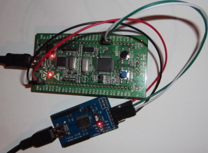
For this, we are going to program USART1 in our STM32VLDiscovery board. Discovery board only comes with naked pins that we must connect to USART-level converters like RS232 or USB. For this example, we will use widely acceptable FT232RL-based TTL to USB converter. So we connect board pins to the converter as follows:
- STM32VLDiscovery PA9 to Rx of FT232RL board
- STM32VLDiscovery PA10 to Tx of FT232RL board
- STM32VLDiscovery 3.3V to VCC of FT232RL board
- STM32VLDiscovery GND to GND of FT232RL board
Using STM32F10x_StdPeriph_Driver library programming task becomes very easy. Let’s use our template from the previous example. This time we will add a couple more files to the project called usart.c and usart.h. Here we will write USART initialization function and byte read and write routines. Let’s start with Initialization:
Initializing microcontroller peripherals
voidUsart1Init(void)

{

GPIO_InitTypeDef GPIO_InitStructure;

USART_InitTypeDef USART_InitStructure;

USART_ClockInitTypeDef USART_ClockInitStructure;

//enable bus clocks

RCC_APB2PeriphClockCmd(RCC_APB2Periph_USART1 | RCC_APB2Periph_GPIOA | RCC_APB2Periph_AFIO, ENABLE);

//Set USART1 Tx (PA.09) as AF push-pull

GPIO_InitStructure.GPIO_Pin = GPIO_Pin_9;

GPIO_InitStructure.GPIO_Mode = GPIO_Mode_AF_PP;

GPIO_InitStructure.GPIO_Speed = GPIO_Speed_50MHz;

GPIO_Init(GPIOA, &GPIO_InitStructure);

//Set USART1 Rx (PA.10) as input floating

GPIO_InitStructure.GPIO_Pin = GPIO_Pin_10;

GPIO_InitStructure.GPIO_Mode = GPIO_Mode_IN_FLOATING;

GPIO_Init(GPIOA, &GPIO_InitStructure);

USART_ClockStructInit(&USART_ClockInitStructure);

USART_ClockInit(USART1, &USART_ClockInitStructure);

USART_InitStructure.USART_BaudRate = 9600;

USART_InitStructure.USART_WordLength = USART_WordLength_8b;

USART_InitStructure.USART_StopBits = USART_StopBits_1;

USART_InitStructure.USART_Parity = USART_Parity_No ;

USART_InitStructure.USART_Mode = USART_Mode_Rx | USART_Mode_Tx;

USART_InitStructure.USART_HardwareFlowControl = USART_HardwareFlowControl_None;

//Write USART1 parameters

USART_Init(USART1, &USART_InitStructure);

//Enable USART1

USART_Cmd(USART1, ENABLE);

}
Here we have a typical situation where we have to take care of enabling peripheral clocks. We know that USART1 is located on APB2 peripheral bus as GPIOA and AFIO. All these are needed because USART1 pins alternate functions of port A. These has to be clocked to use them:
RCC_APB2PeriphClockCmd(RCC_APB2Periph_USART1 | RCC_APB2Periph_GPIOA | RCC_APB2Periph_AFIO, ENABLE);
Next task is to set up USART pins where Tx pin should behave as alternate function push-pull while Rx is floating input. Once pins are set, we need to take care of the USART clock. As we are going to use a standard set up, we can use function helper that does this by setting default values:
USART_ClockStructInit(&USART_ClockInitStructure);
USART_ClockInit(USART1, &USART_ClockInitStructure);
Writing USART functions
Then we can set up USART-specific settings by selecting baud rate, data word size, stop, and parity bits, and enable Rx and Tx modes. All this is done by setting values in USART_InitStructure, as seen above. The last command enables USART1. From this moment, USART1 is up and ready. Now we can proceed to send and receive data functions:
void Usart1Put(uint8_t ch)
{
      USART_SendData(USART1, (uint8_t) ch);
      //Loop until the end of transmission
      while(USART_GetFlagStatus(USART1, USART_FLAG_TC) == RESET)
      {
      }
}
uint8_t Usart1Get(void){
     while ( USART_GetFlagStatus(USART1, USART_FLAG_RXNE) == RESET);
        return (uint8_t)USART_ReceiveData(USART1);
}
We call them Usart1Put and Usart1Get functions that transmit and receives data bytes. You can see in both functions that it is essential to wait for transmission complete before sending the next byte or storing received data. At the same time, loops check for proper flags to be set.
In the main program, we can call these functions to send and receive single bytes of data as follows:
#include "stm32f10x.h"
#include "usart.h"
int main(void)
{
Usart1Init();
Usart1Put('A');
Usart1Put('R');
Usart1Put('M');
while (1)  {  }
}
Being able to send a single byte is a good start, where you can wrap this function with loops to send strings and so on. But what about sending numbers or specially formatted strings that would include some variable data. Writing these functions would be time-consuming and meaningless because this has been done a long time ago and is widely used. These are called iostream functions, where data is sent by using standard streams with functions that allow formatting strings as you like.
I/O streams originally were designed to support operating systems where data could be read from the keyboard and sent to display or another output device. It seems that they fit well in embedded systems, too, with some tweaking.
GCC toolchain uses a newlib C library that originally is used in Redhat, and therefore it’s not adapted for microcontrollers there is no operating system. (Opposite situation is with AVR GCC tools where avrlibc is specially adapted to support AVR microcontrollers and works out of the box). So when we start dealing with OS-dependable functions, we face some stubs. Stubs are called system call functions that are served by the operating system.
In microcontroller, there is no OS. These functions face dead-end, leading to compile errors. The fundamental trick to avoid this is to take care of these syscalls by writing some implementation where many of them can be the dummy. Understanding them all and writing your implementations would be too hard – at least in the beginning, so there are ready sources that can be used. I prefer to start with newlib_stubs.c developed by nanoage.co.uk. This seems to work fine with I/O stream functions. There are dozens of other system functions, but most important are _write(), _read(), and _sbrk(). The _write function takes care of writing characters to stdout, and stderr; _read() is to read from stdin; and _sbrk() is needed for malloc-related functions where it is important to know if dynamic memory doesn’t collide with the stack. In _read() and _write() functions, we need to implement our byte send and read functions so when we call printf() function, we could output string to USART:
int _read(int file, char *ptr, int len) {
    int n;
    int num = 0;
    switch (file) {
    case STDIN_FILENO:
        for (n = 0; n < len; n++) {
            char c = Usart1Get();
            *ptr++ = c;
            num++;
        }
        break;
    default:
        errno = EBADF;
        return -1;
    }
    return num;
}
And for writing to stdout and stderr:
int _write(int file, char *ptr, int len) {
    int n;
    switch (file) {
    case STDOUT_FILENO: /*stdout*/
        for (n = 0; n < len; n++) {
            Usart1Put(*ptr++ & (uint16_t)0x01FF);
        }
        break;
    case STDERR_FILENO: /* stderr */
        for (n = 0; n < len; n++) {
            Usart1Put(*ptr++ & (uint16_t)0x01FF);
        }
        break;
    default:
        errno = EBADF;
        return -1;
    }
    return len;
}
Simply speaking, you can direct streams where ever you want (LCD, SPI, I2C, etc.) by putting send/receive byte functions here.
Testing USART code with the terminal screen
After setting this, we can send formatted strings and read any data by using studio functions:
#include "stm32f10x.h"
#include "usart.h"
#include <stdio.h>
int main(void)
{
    char ch[30];
    int32_t a1,a2;
    Usart1Init();
    printf("\r\n USART1 Test \r\n");
    printf("Enter any text: ");
    scanf("%s",ch);
    printf("\r\nYou entered: ");
    printf("%s\r\n",ch);
while (1)
  {
    printf("\r\nEnter first number: ");
    scanf("%ld",&a1);
    printf("%ld", a1);
    printf("\r\nEnter second number: ");
    scanf("%ld",&a2);
    printf("%ld\r\n", a2);
    printf("Sum: %ld + %ld = %ld\r\n",a1, a2, a1 + a2);
  }
}
And results in the terminal screen:
In the next part, we will be dealing with interrupt-based buffered communications.


Hello! I start to use STM32-VL-Discovery. Can you download (or take links) for this project. When I try to compiling my project with newlib_stubs.c many errors, such as ..\..\..\STM32_VL_Discovery_Libraries\newlib-1.20.0\newlib\libc\include\sys/types.h(110): error: #256: invalid redeclaration of type name “time_t” (declared at line 70 of “C:\Keil\ARM\RV31\INC\time.h”) appears. Maybe, I do not correct use this library… My goal – is write to COM-port of PC some “words” from STM32, not only symbols (chars) as function printf() work (by example).
i need more basic commands in the program belongs to the beginners…
Hello, I used your method but program always stop at scanf(), terminal type any word still stop, until the TX more than 1024 bytes, then the program will run next step. What ascii code will let scanf conclude ? How could I do ?
What is dummy ISR When i was working on USART1……
I have been working from two to solve this error. Can any body know about this.
Code::Blocks with Embedded Plugin Suite is
nice environment for STM32 development including ARM GCC compiler STM32 project wizard (including lot of STM32 discovery examples) debugger supporting ST-Link / V2 and Serial wire viewer for output of debug messages in runtime. All discussed jobs here can be easily performed.
Hi ! I have message Heap and stack collision 🙁
hi,
currently im working on STM32F103R8 in this i did the Tx/Rx using usart1 by the same procedure u did here,then instead of usart1 i used usart3 but it doesn’t give the output,not even the pin is initializing.What to do is there any special procedure for usart3?
Did you enable peripheral clock for usart3?