Connecting multiple I2C devices on a common bus
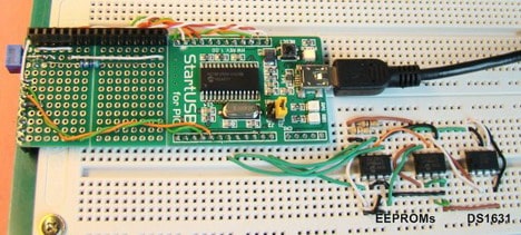
The I2C communication protocol is so popular today that you can buy varieties of I2C-compatible devices in the form of temperature sensors, serial EEPROMs, real-time clocks, LCD drivers, port expanders, and so on. While most modern microcontrollers do have built-in I2C communication ports, its implementation requires a good understanding of the protocol in general, its signal types, and an addressing scheme for uniquely identifying multiple devices on a common I2C bus. Embedded Lab’s new tutorial on I2C communication covers all the detail that is required for connecting multiple devices on a common I2C bus. The tutorial uses the PIC18F2550 microcontroller, to which is connected three I2C compatible devices: 2 EEPROMs (24LC512) and one temperature sensor (DS1631). In the experiment, the microcontroller receives the temperature readings from DS1631 sensor and stores them in the two EEPROMs. Later, the readings are retrieved from the EEPROMs and displayed on an LCD screen. More about I2C capabilities The number of I2C devices that can be connected to a microcontroller depends on the number of available I2C bus lines, the addressing scheme used by the…